My 4-way switches don't work!
You set out to replace some or all of your switches in a circuit controlled by three or more. You cannot remember how they were wired, and now things do not work.
(If you only have two switches in your circuit, see instead My 3-way switches don't work.
What do you do?
First, you may find it helpful to understand how 3-way and 4-way switches work to accomplish this task. See Controlling a light with two or more switches. Further, this discussion assumes that you have only disconnected the switches and have not removed wire nuts from any other connections inside the switch boxes.
Note that there are 3-way switches at each end and one or more 4-way switches in the middle. For this discussion, let's assume only one 4-way switch.
Analyzing the circuit
We need to answer the following questions:
- For the first 3-way box, which two of the three wires attached to the original switch continue to the 4-way?
- Same as above for the second "3-way".
- In the 4-way box, which of the 4 wires attached to the 4-way switch form a pair leading to the first 3-way switch?
- What is the wiring pattern of your new 4-way switch?
- What is the wiring pattern of your 3-way switches?
You generally need two people working together answer these questions:
one with a multimeter on resistance, one tapping pairs of wires
together. Any multimeter with a resistance scale will work. You should be able
to find one at Radio Shack for ten or fifteen dollars.
First, kill the circuit breaker and be sure there is no power to the circuit.
Next remove all three switches.
To answer Question 1:
Post person A at the first 3-way box and person B with the meter at the four way box. B measures the resistance between various pairs of the 4 wires as A taps together various pairs of the 3 wires. When B sees the resistance alternating between zero and infinity as a pair of wires is tapped, you have identified the pair of wires going from the first 3-way box to the 4-way box.
To answer Question 2:
This is easier, because the remaining pair of wires in the 4 way box leads to the second 3-way box. Place A at the 4 way box and send B with the meter to the 3 way box. Have A tap the (second) pair of wires in the box together as B measures the resistance between pairs of wires in the 3-way box, until the connecting pair is identified.
To answer Question 3:
This was already answered as part of answering question 1.
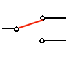
To answer Question 4:
 We
will now make measurements on the isolated 4-way switch, with the switch out
of the circuit. Place one lead of the multimeter on any single screw of the
switch. Measure the resistance to each of the other screws in each switch position
until you find the one screw that shows infinite resistance to the first screw
in both switch positions. Call this screw and the first screw the "IN"
pair. Call the remaining screws the "OUT" pair.
We
will now make measurements on the isolated 4-way switch, with the switch out
of the circuit. Place one lead of the multimeter on any single screw of the
switch. Measure the resistance to each of the other screws in each switch position
until you find the one screw that shows infinite resistance to the first screw
in both switch positions. Call this screw and the first screw the "IN"
pair. Call the remaining screws the "OUT" pair.
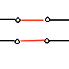
To answer Question 5:
 Find
the pair of screws that always show high resistance with the switch in either
position. Call these the "OUT" pair. The remaining screw is the "IN"
screw of the 3-way switch. Double check: the resistance from the "IN"
screw to either "OUT" screw will toggle between 0 and infinity as
the switch is flipped. Note: if one screw is a different color from the other
two, this is probably the "IN" screw.
Find
the pair of screws that always show high resistance with the switch in either
position. Call these the "OUT" pair. The remaining screw is the "IN"
screw of the 3-way switch. Double check: the resistance from the "IN"
screw to either "OUT" screw will toggle between 0 and infinity as
the switch is flipped. Note: if one screw is a different color from the other
two, this is probably the "IN" screw.
OK!!!!!
Wiring the switches
Now you are ready to wire the switches. Refer again to the figure on the Controlling a light with two or more switches page.
- In the 4-way box, connect the pair of wires from the first 3-way switch to the "IN" pair of screws of your 4-way switch. Order is not important. Connect the other pair of wires (which lead to the second "3-way" switch) to the other pair of screws.
- In the first 3-way switch box, connect the pair of wires leading to the 4-way box to the "OUT" pair of screws on the switch. Connect the remaining wire to the "IN" screw.
- Repeat for the other 3-way switch box.
The circuit should now work.
- Controlling a light with two or more switches, a discussion of how 3-way and 4-way switches work.
- Rick Matthews home page.
- Rick Matthews' miscellaneous tips and info.
- Department of Physics.
- Wake Forest University.